Go to Otherpower.com Home Page Go to Forcefield Shopping Cart Go to Wondermagnet.com Home Page
Front Page - [Homebrewed Electricity-- (wind) (solar) (hydro) (controls) (storage) (mechanical)] - Classifieds - Site News
Everything - Newbies - [Remote Living-- (housing) (heat) (light) (water)] - Rants & Opinion - Diaries - Our Products
Building my first real windmill (Part 1)


By Ahto, Section Diaries
Posted on Sun Jan 21st, 2007 at 04:13:18 PM MST
A starting project towards some serious wind power. First part of the series ;) includes nice pictures!

Actually it's not my first windmill, I have built several toy windmills as a child and also occasionally attached small PM DC motors to them to watch the voltmeter dance during gales.

Nevertheless this is the first one with some theoretical background involved and variety of wood and metal work skills put to use. The goal of this project is getting familiar with the workings of a power generation windmill and to make most of the mistakes before scaling everything up. Therefore as efficiency of the mill is not crucial I opted for the first choice every beginner would - using a car alternator, thereby making this story a practical walk through of such a poor choice for all the newbies.

So let's see what's the best we can get out of this - here goes nothing ...

First thoughts ...

First thoughts considered putting the windmill rotor shaft on some durable bearings and then gearing up the alternator with bicycle gearwheels and chain or something similar depending what I would have come across and building everything else from there. This would suggest quite a large blade diameter to harvest enough energy hoping to gear up the rotation but since I didn't want things to get too large for now and had only 100x50 mm studding laying around I maid rather ignorant decision to start with 1,5m diameter blades.

Oh, by the way, as I have to cope with all the English units everywhere I will bless you all with my metric ones this time ... (grin!)

Blades

So as the first thing I started graving out the blades. Sadly I didn't took any pictures of the process but it looked the same as in all the tutorials on the web and in books anyway. Although here's a picture of me posing with the finished rotor.


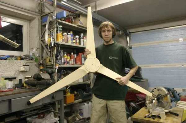
Making the blades went really fast. First I used formulas from the Piggotts book "Windpower Workshop" to calculate everything needed and then spent half of a day and another evening making one blade. It turned out though that wood work with such a precise shape in such a small scale is quite tricky so I turned to Otherpower's design suggesting using only strait lines form tip to root. Ii took then one day to make all three new blades. Electric planer speeded things really up.

Alternator

Then on one evening I walked to the nearest junkyard and got myself an Opel Rekord's alternator from year 83'. Costed me 300 EEK (about $25) and looked like it had fallen off by itself, not taken off (horrible!). Well it was the cheapest working one.

It's a Bosch brand rated for 14V, 45A. After little cleaning I started making some tests spinning it around with hand drill.


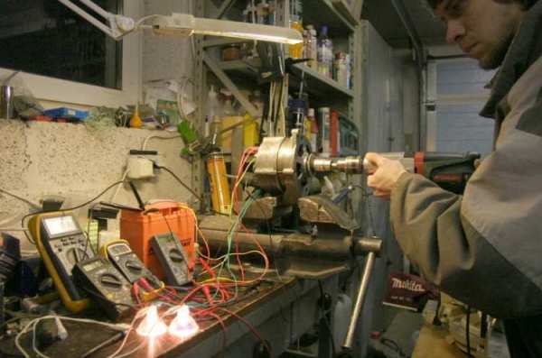
I used several different wattage 12V halogen bulbs to load the alternator and measured field coil current, output current, voltage and frequency to calculate RPM. The battery was used to excite the field coil before the alternator was producing enough current by itself.

Now about the main concerns regarding car alternators.

The voltage regulator is not suitable in wind power. True of course. But I was thinking, if I use shunt regulator keeping the voltage a little under the rated voltage of the alternator's regulator it wouldn't kick in during normal operation but would still be there to protect the alternator from burning out itself if other controls fail. Not surprisingly bad idea still! I think it depends on the type of the regulator but I didn't realise how suddenly it cuts off the load. Hench if just a little inaccuracy in other controls let the voltage to rise over 14V just for once the voltage regulator would cut off field current leading to unstoppable runaway. Fortunately it's easy to by-bass the regulator.

Then the field coil needs exiting when the alternator has gathered enough speed. Not very hard to devise such a system but it still eats up all your power in low winds just to keep the darn thing exited. I think it would be all the better replacing the field coil with microwave oven magnets - and I'm planning to do just that.

Finally the worst part - high RPM required. Well it doesn't seems so bad at all in my case. Regrettably I didn't made any exact notes during the testing because I wasn't really sure of anything, just wanted to get a overall picture but I will make some more tests soon and keep you posted. Still I noticed that the RPMs didn't rise to hight instead torque started to increase with the load. Maybe it's that the alternator is from a car old enough that doesn't know such high RPMs so the alternator must be a little bit better just to get something out of it.

Now looking at a spreadsheet showing RPMs and power for my blades at a given wind speed things look quite fair. Assuming no gearing cut-in speed would be somewhere at 7 m/s and getting up to 100W in winds 10 m/s seems fair enough for such a small mill that's not even meant to produce real power.

Construction of the windmill

So I discarded the idea of gearing and started building.


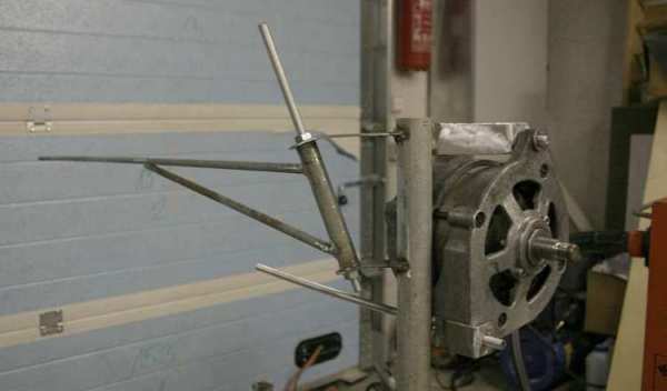
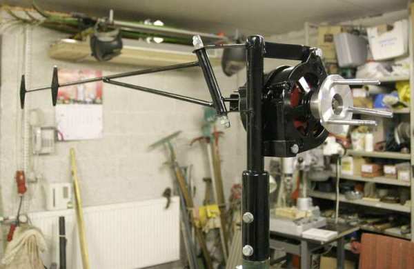
Not much to say here, it's Piggot's furling tail design. Rotor center is ~80mm off from the yaw axis and the tail hinge is aligned at about 20 degrees and 45 degrees away from the rotor axis. Tail stops and yaw bearing are jet to be added.


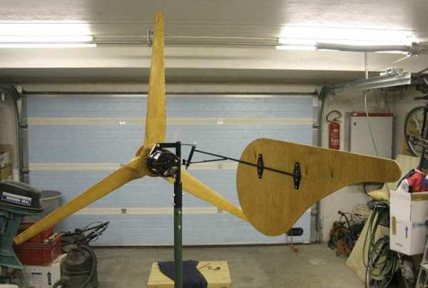
And here it's all put together. Let's take a closer look on it on next pictures.


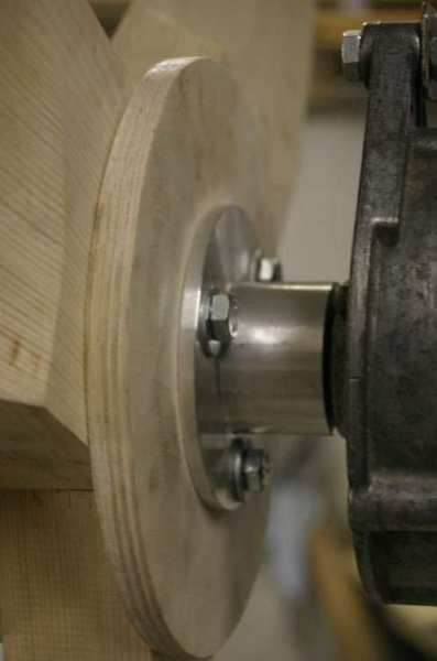
This is how the rotor is mounted on the alternator shaft. The flange is machined out of aluminium. The shaft is threaded and a nut fits inside the flange. Then the rotor is simply bolted on. I don't know if the alternator bearings would hold up, time will tell ...

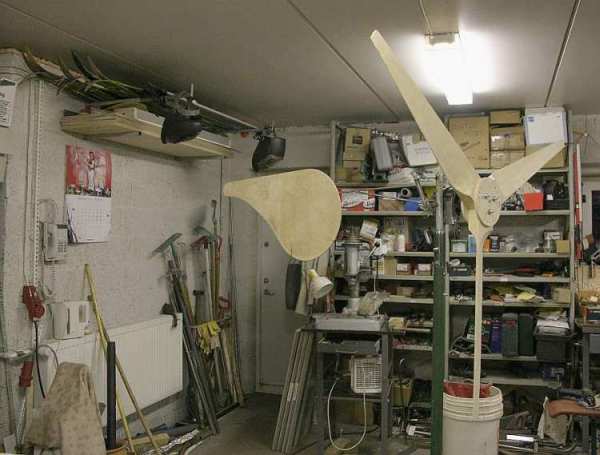
In the mean while I managed to paint the thing.


You can see stops for the tail added. The yaw "bearing" is made of different sized pipes. First a PVC pipe is precisely fitted inside the outer steel pipe so it stays put because steel pipes are quite rough inside. Then a smaller steel pipe which is welded on the fat mounting pipe is greased and fitted inside the PVC one. This gives nice free and smooth movement without slacks. I don't think the PVC pipe wears out faster than any other moving part.


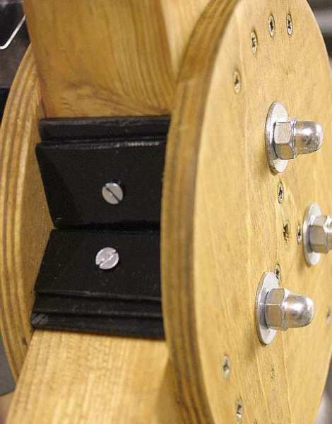
Blades are balanced with those pieces of steel screwed to the rotor. And the whole thing is finished on following pictures.


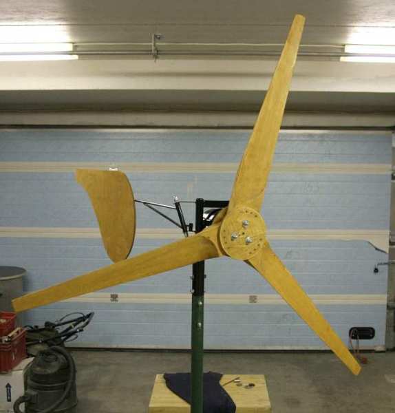
I took two full days all together to build all this. After that it was finally time for some test flight!


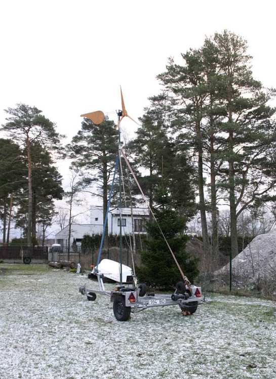
Ehmmm ... yes, that is a boat trailer! I think one can really see the anticipation to get the mill up. :) The trailer is wide an heavy enough for not dipping over and the winch was already in place, I only removed one of the bottom rollers and mounted my tower - what a great portable tilt-up tower!

The mill was up and flying in an hour and I measured some 300-400 RPM and 6-8V into 0,5W load in a light breeze with the field coil powered by battery.


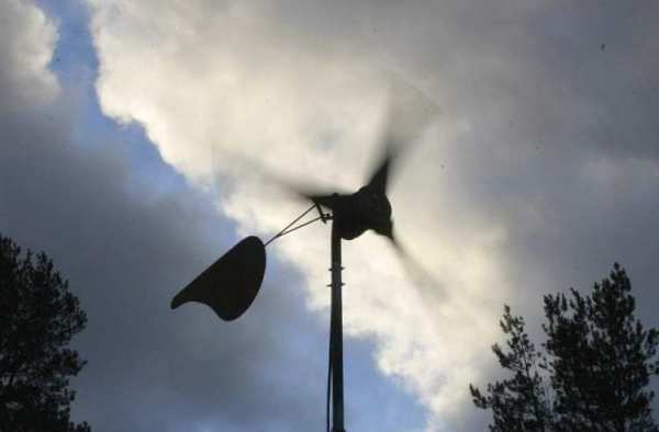
As of 21.02.2006 the mill is up in the backyard free running just for amusement since there's hardly any wind to do anything useful. Just as someone has stated somewhere: there's a total calm for several weeks after you have gotten up you first mill!

What's next

Of course things are long way from finished. There's no load control whatsoever although I'm working on it at the moment and those 6-8V into 0,5W ain't getting us nowhere so the alternator is up for modification to PM alternator and maybe some rewinding. I'll keep you posted!

Also there's some more larger size pictures over here kuu.pri.ee/pub/tuulikud .

Building my first real windmill (Part 1) | 22 comments (22 topical, 0 editorial)

Re: Building my first real windmill (Part 1) (3.00 / 0) (#1)
by Flux on Sun Jan 21st, 2007 at 10:21:06 AM MST
(User Info)

Nice work and nice blades.

You will need to rewind with about twice the number of turns and half the csa wire to get the speed down to suit your 1.5M prop.

If you want any output below 7M/s you will need to replace the wound field with neos.

All good experience, you will eventually find it less work and you will get better results if you build a PM alternator from scratch. Even a small motor conversion will have a bigger core and give you better results than that car alternator, but we all have to start somewhere.

Keep us posted with the results.
Flux


Re: Building my first real windmill (Part 1) (3.00 / 0) (#2)
by Ahto on Sun Jan 21st, 2007 at 10:36:27 AM MST
(User Info)

Oopps! I spotted a strange mistake. As of 21.01.2007 (not 21.02.2006!) is the mill up! Don't know how this got in :D Well, I have never been good at numbers ;)


Re: Building my first real windmill (Part 1) (3.00 / 0) (#3)
by wil (lwthexsterATgmailDOTcom) on Sun Jan 21st, 2007 at 11:48:55 AM MST
(User Info)

Hi Ahto,

The craftsmanship is very good along with the pictures and narrative.

Stories like this are amongst my favorite here on this board. It's interesting to see the progress and evolution of a project.

Wil


Re: Building my first real windmill (Part 1) (3.00 / 0) (#4)
by zubbly on Sun Jan 21st, 2007 at 01:47:24 PM MST
(User Info)

hello Ahto,

congratulations, i think that is an excellent attempt and encourage you to keep on building. its a lot better looking machine than my first ones i tell ya  :)

just some thoughts.

have you taken the alternator apart? if not, it may be worth a look inside.  many auto alternators are connected delta, and if you re-connect it star, it will reduce your cut in rpm needed and raise your output voltage per rpm.

just another thought. if you are successful in re-connecting the unit to star, keep in mind that your voltage from one output line to the star point will give you 58% of the line voltage. so if you are charging a 12 volt battery (the battery will keep the line voltage of the alternator to that of the battery) you could tap off a line from one of the output lines and one from the star point. this will give you approx 7 volts that you can run to a small bridge rectifier to power the field coil.  its kinda down and dirty, but it is a way of reducing the rotor field strength and perhaps allow you to tweek the system a bit. i am also not sure if there will  be any residual magnetism left in the rotor to get the unit going, so you could perhaps put a excitation button from the battery in order to start the unit with a momentary circuit.

its just outloud thoughts.  may work or may not.  having fun trying is what counts :)

good luck,
zubbly


Re: Building my first real windmill (Part 1) (3.00 / 0) (#5)
by Norm (peppysue@suite224.net) on Sun Jan 21st, 2007 at 06:37:15 PM MST
(User Info)

Oh, by the way, as I have to cope with all the English units everywhere I will bless you all with my metric ones this time ... (grin!)

 Metric stinks! (personal opinion) ( :>)
  Nice Job tho'
             ( :>) Norm.


Re: Building my first real windmill (Part 1) (3.00 / 0) (#8)
by Flux on Mon Jan 22nd, 2007 at 01:54:10 AM MST
(User Info)

After many years after the change here, I find that in general metric is more logical and for those brought up with it it is better,

Some metric units are awkward but so are most imperial. I tend to use a mixture of both.

At least with metric we don't have the totally stupid variation between North American and English. Your gallon is different, the wire gauge is different and I have to convert many of your imperial units and unless specified I have no idea which are meant.

This is particularly true with hydro when gallons are quoted. ( which ones).

For wind and electrical calculations metric is far easier, the answer comes out directly in Watts without going to horespower ( which again is a bit variable between countries).

I don't like the Pascal or the Weber, I can't think in 10 to the minus umpteen but generally metric is fine. Fractions are ok up to about 1/16 but I wouldn't have a clue what 17/64 was.

Flux

[ Parent ]


Re: Building my first real windmill (Part 1) (3.00 / 0) (#6)
by luckeydog (bryan@coloradowindpower.com) on Sun Jan 21st, 2007 at 08:49:34 PM MST
(User Info) http://www.coloradowindpower.com

I love your idea of using a trailer. you could tow it around behind your truck on a calm day and do some testing with it.
 If you have already done so, did you have any problems with tipping?

nice work I also love reading post like thees.
wind gens are much funner to watch than solar panels.


Re: Building my first real windmill (Part 1) (3.00 / 0) (#7)
by coldspot on Sun Jan 21st, 2007 at 09:45:38 PM MST
(User Info)

Super nice craftsmanship
Very nice work
Bad pick of what to use and try but
 trying is better than not.
Induction conversion or scratch build
from the work posted you could be building some nice
air gaps, you must have a great shop and tools at your disposal.
:)


Re: Building my first real windmill (Part 1) (3.00 / 0) (#9)
by margusten (margusten.ee@mail.ee) on Mon Jan 22nd, 2007 at 02:41:28 AM MST
(User Info) http://www.geocities.com/ResearchTriangle/Thinktank/1780

Hi Ahto,

Nice to hear that I am not only Estonian here.

I rewind similar auto alternator with thinner wire. Three time more windings than original. Put 12 round magnets inside it. But result was not good. Too small magnets and airgap much bigger than original and cogging little bit. Half year after that I disassemled it and reused these round magnets in my new windmill:
http://www.fieldlines.com/story/2006/9/7/9813/95679

This 1.5m diametre windmill working good. I can see up to 2A current to 12V battery in high winds and 0.5A in 8km/h wind, open voltage 50V in high wind. Still not much useable power. My mistake was too thin wire in this stator. I have to rewind with 1.6mm wire.

Now I am building real windmill from car front break parts. Unfortunately not much time for it.

BR,

Margus


Re: Building my first real windmill (Part 1) (3.00 / 0) (#10)
by Jerry on Mon Jan 22nd, 2007 at 09:18:24 PM MST
(User Info) http://www.dplusv.com/Photo-03.html

Hi Ahto.

Here are a few pictures of modifications I've made to GM car alternators to reduce rpm and wind speed requierments.

First is to change the wireing scheem to this.

Here is the stator after modifications.

Next I use an armature from an ac motor ocupide with small 1/2"X1"X.25 NEO magnets. This makes for bad cogging but scewing would help reduce that. I also use 2 alternator front faces. This helps acomidate the ac motor armature.

Well can't find the picture I'll post it latter?

Here is the 2 faced alt.

Heres another alt in the Laithe. 6 wires comming out.


                         JK TAS Jerry

Airheads Page


[ Parent ]


Re: Building my first real windmill (Part 1) (3.00 / 0) (#11)
by Jerry on Mon Jan 22nd, 2007 at 09:22:02 PM MST
(User Info) http://www.dplusv.com/Photo-03.html

OK I see what went wrong. I'll try it again.


                       JK TAS Jerry

Airheads Page


[ Parent ]


Re: Building my first real windmill (Part 1) (3.00 / 0) (#12)
by Ahto on Tue Jan 23rd, 2007 at 01:49:41 AM MST
(User Info)

Thanks to everyone from commenting.

<u>To Flux</u>
Building a PM alternator from scratch was already planned before I started this project so the power of this small mill isn't very important but I wanted to get to know the furling system and load control details before going big. Still I'm planning to convert and rewind this car alternator just for the fun of it! :)

<u>To zubbly</u>
Yes, I have took the alternator apart. It's already star connected. The field coil I'm not worried about because this is going to be replaced by PMs anyway.

<u>To luckeydog</u>
No, haven't towed the trailer around yet and certainly won't do it on the road with the mill up! :D But if the wind wouldn't take up enough for some overload testing I might tow it to more open fields nearby.

<u>To margusten</u>
Were those magnets neos that you used to convert your alternator?

<u>To Jerry</u>
As far as I'm concerned yours schematic is in principle same as delta connection but with more diodes. Did you rewind the stator?

Ahto


Re: Building my first real windmill (Part 1) (3.00 / 0) (#13)
by Jerry on Tue Jan 23rd, 2007 at 09:17:29 AM MST
(User Info) http://www.dplusv.com/Photo-03.html

Hi Ahto.

The schematic posted is not equal to delta or star. Star is equal to 2 phase in sires but with a voltage drop. Delta is equal to 3 phases wire perelell no voltage drop.

The schematic I posted is equal to 3 phases wired sires with no voltage drop.

The stator is stock wireing. This reduces rpm requierments drasticly.

                         JK TAS Jerry

Airheads Page


[ Parent ]


Re: Building my first real windmill (Part 1) (3.00 / 0) (#14)
by Flux on Tue Jan 23rd, 2007 at 09:58:47 AM MST
(User Info)

Did you upload the diagram you intended Jerry.

As shown it will require higher speed than star.

Flux

[ Parent ]


Re: Building my first real windmill (Part 1) (3.00 / 0) (#15)
by Jerry on Tue Jan 23rd, 2007 at 10:58:29 PM MST
(User Info) http://www.dplusv.com/Photo-03.html

Hey Flux thanks for bringing that to my atention. No I goofed. My bad. Best wear my glasses next time. Truble is my main computers is down. It has the right picture/schematic in it. I better find it soon or I'll look real silly posting the wrong picture.

I think Ed has the schimatic on his site also.

Sorry guys. Thanks Flux, way to keep an eye on things.

                           JK TAS Jerry

Airheads Page


[ Parent ]


Re: Building my first real windmill (Part 1) (3.00 / 0) (#16)
by wooferhound (tim((NoSpamAt))wooferhound.com) on Wed Jan 24th, 2007 at 03:16:09 AM MST
(User Info) http://wooferhound.com


W o o f -={(

[ Parent ]


Re: Building my first real windmill (Part 1) (3.00 / 0) (#18)
by Ahto on Wed Jan 24th, 2007 at 07:05:58 AM MST
(User Info)

Hi wooferhound,

This schematic looks bit more useful than the previous one. It's probably covered in detail somewhere else on the board but can someone point out for short where's the catch. Why aren't everyone using it.

Ahto

[ Parent ]


Re: Building my first real windmill (Part 1) (3.00 / 0) (#19)
by Flux on Wed Jan 24th, 2007 at 07:48:46 AM MST
(User Info)

Too many volt drops in series diodes and to be any use the capacitors have to be monsters ( 20, ooo uf  plus)

If you use schottky diodes and don't mind the cost of capacitors it is an alternative to rewinding. Not a first choice for an original winding.

Flux

[ Parent ]


Re: Building my first real windmill (Part 1) (3.00 / 0) (#17)
by margusten (margusten.ee@mail.ee) on Wed Jan 24th, 2007 at 05:50:40 AM MST
(User Info) http://www.geocities.com/ResearchTriangle/Thinktank/1780

Hi Ahto,

12 Neodym 35 dia 14x8mm round magnets I bought from Tevalo. (600EEK)
You need 2-3 times bigger magnets to get good power out of generator.
http://www.tevalo.ee/cgi-bin/web_store.cgi?page=!37-520-52
I have no pictures of this auto(car) alternator modification, but it looks exactly like Jerry-s, only round magnets instead of rectangular ones.
Of course rectangulat magnets are much better.
Cheapest source of neo magnets here I found - old hard discs.

Margus


[ Parent ]


Ooops! RIP car alternator (3.00 / 0) (#20)
by Ahto on Tue Jan 30th, 2007 at 12:10:39 PM MST
(User Info)

Hi again folks!

Here's some update. I promised some test results for that car alternator seen above.


 RPM       Amps
 ------      ------
   800      0,4
   880      1,3
   950      1,7
   975      2,7
 1000      3,7
 1005      4,4
 1015      4,9
 1030      5,2
 1035      5,8
 1045      6,3


 Volts were 14,5 in all cases.

This was measured on the output with the alternator powering field coil by itself. As can be seen, it would have suited my prop nicely around 7-10 m/s.

Unfortunately this test was the last thing that alternator would ever produce 'cause I continued with modifying it to PM alternator.


"Car alternator for dummies" :P


So I had few of those magnetron magnets laying around and figured that the easiest thing to do would be putting them in place of the original field coil. Well it wasn't easy neither was it wise. Now looking at it it's obvious that there's probably massive flux leakage directly between the "fingers" of the rotor and even without that they were far too weak. RIP car alternator.

At the moment the alternator chassis serving as set of bearings is still up on the tower for the mill to amuse everyone just freewheeling there. The furling system has proven to work although not known at what speed and the boat trailer hasn't dipped over, so that's still good.

As for now I'm planning to build a small axial flux alternator from hard disk magnets to suite my present prop and to continue with tweaking the tail and controls. Would you guys think it be wise to use the alternator chassis and fit the axial flux design inside or would the diameter be too small or something? I'm thinking of 8 poles and 2 coils per phase (3-phase) and aim for 14 volt cut-in. I would use two rotors and double magnets meaning I would cut hard disk magnets in half putting one half on top of other and then place 8 such sets on both rotors.


Re: Ooops! RIP car alternator (3.00 / 0) (#21)
by jimovonz on Tue Jan 30th, 2007 at 12:19:15 PM MST
(User Info)

The gap between the fingers should be considerably less than the gap between the fingers and the laminations. When the rotor is inplace you should get minimal leakage (at least no more than occured with the original field coils). I have had good luck 'recharging' the ceramic magnets from a microwave by placing them on a large neo. In most cases it produces a measureable increse in flux from the ceramic after it is removed. I would be interested to see the output of such a setup...

[ Parent ]


Re: Ooops! RIP car alternator (3.00 / 0) (#22)
by Ahto on Tue Jan 30th, 2007 at 12:41:32 PM MST
(User Info)


> The gap between the fingers should be
> considerably less than the gap between
> the fingers and the laminations.

Ohoo? The cap between the fingers was 3-4 times the cap between laminations. Even in original condition. Interesting ...

[ Parent ]


Building my first real windmill (Part 1) | 22 comments (22 topical, 0 editorial)
Display: Sort:
Menu
· create account
· How to use the board
· FAQs
· search the board
· Google search the board
· Old Otherpower Board

Login
Make a new account
Username:
Password:

Total Views
  176 Scoop users have viewed this posting.

Related Links
· magnet
· kuu.pri.ee/pub/tuulikud
· Ahto's Diary

Powered by Scoop
You must be a registered user to post here. It's easy and free, and the link is on the upper right side of your page.
All trademarks and copyrights on this page are owned by their respective companies. Postings are owned by the poster, but may be deleted or moved at the ADMIN's sole discretion. The Rest © 2003 Forcefield.
You can Email the board ADMIN here. PLEASE include the username you signed up with!